Logo
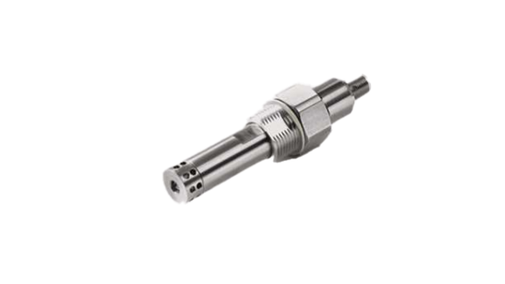
FRG00032 1024 Square

Water in Oil Sensor (WiO)

The Water in Oil system from HORN consists of a sensor FRG00032, a connection box GHG02088-5, a connection cable KSG03244-1, and three relay outputs. Additionally, to the basic standalone version, is the option to get an analogue output for water content and oil temperature, as well as an indicator box with analog indicator(s), operating devices, and an acoustic alarm.

The WiO benefits you with:

  • Water in oil saturation monitoring
  • System protection
  • Service on request
  • Precision engineered
  • Harsh environment capability.

For sales or commercial inquiries please contact us at marine@insatech.com.

Contact us now

How does the WiO system work?

Oil can hold a certain amount of dissolved water, where the maximum amount of water that oil can hold is characterized by the "saturation point". Above this point free water precipitates, which can lead to corrosion inside your engine.

Traditionally, you would measure the free water in your oil or emulsion, but the WiO system system senses the absolute content of absorbed water in oil. Thus, the Water in Oil Sensor FRG00032 physically detects the water activity based on the capacitive measuring principle.

Because the WiO system is installed in a vigorous stainless-steel housing the sensor resists the most demanding environmental conditions.

Moreover, you get a highly flexible system that offers a simple integration with the sensor and the connection and processing unit (GHG02088-5 or MPU010) with several options for output signal and functions for event memory.

Additionally, the AC version together with the processing unit GHG02088-5 gives you the possibility of not only reading the analog signals of temperature and AW, but also the alarm signals supported by relay technology.

OBS: A great feature of the sensor FRG00032 is the fact, that it does not need any cleaning.

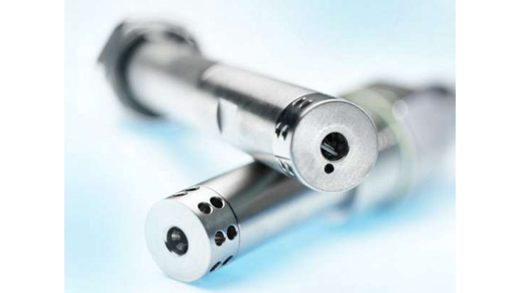
FRG00032 Sensorshaft68 1024 16X9

The WiO system consists of:

The Water in Oil System from HORN consist of:

  • Sensor FRG00032
  • Connection and processing box GHG02088-5 or MPU010
  • Connection cable KSG03244-1

Additionally, to the basic standalone version, is the option to get an analogue output for water content and oil temperature, as well as an indicator box with analog indicator(s), operating devices, and an acoustic alarm.

Need our help? Contact us now.

Typical Applications:

The WiO system is applicable in various fields including:

  • Marine engines
  • Power generation
  • Oil transformers
  • Hydraulic aggregates
  • Large gear units
  • Heavy duty applications.

Do you have any questions? Contact us

FRG00032 1 1024 16X9

Two Different Sensor Shafts

The WiO sensor is available with two different lengths of the shaft; A sensor shaft with the length of 68 mm or 138 mm.

Sensor Shaft Length 68 mm

Sensor Shaft Length 138 mm.


3 Available Main Processing Units

See the technical data for the main processing unit: MPU010-I-K, MPU010-I-G, and GHG02088-5 below.

MPU010-I-K
Power supply

8 ... 32 VDC, max. permissible ripple ≤ 5 % (protected by automatic fuse)

2 power supply inputs (redundancy)

Power consumption

approx. 10 W

Polarity protection

Yes

Operating/ Storage temperature

-25 ... +85 °C

Relative humidity

< 90 %, non-condensing

Weight

Approx. 1000 g.

Protection degree

IP 67

EMC-standard

DIN EN 55016 and DIN EN 55022, safety rules acc. EN 61000-4, -6 rules for type approval test accord. GL

Connection to PE

Copper mesh band

Cable glands

M12 for sensor
M 12 for power supply M12 for relays
M12 for analog out
M12 for CAN bus
Cable size M12: ø5 ... 6.5mm

Sensor interface

I2C

Relays

PAV (pre-alarm-value), MAV (main-alarm-value), STATUS
Photo-MOS output: < 60 VDC, 500 mA (Short Circuit Protected SCP)

Analog output

current output or voltage output (details configurable: 4-20 mA or 0-10 VDC, others on request), galvanic isolated, user selectable

Current output load

max.1200 Ω

Ethernet

Transmission rate max. 100 Mbit/s, galvanic isolated, IP-Address adjustable

CAN

Transmission rate 20 kBaud ... 1 Mbaud, galvanic isolated, Node ID adjustable 1...127

Configuration/ display

CAN open-protocol / Web page over ethernet

MPU010-I-G
Power supply

8 ... 32 VDC, max. permissible ripple ≤ 5 % (protected by automatic fuse)

2 power supply inputs (redundancy)

Power consumption

approx. 10 W

Polarity protection

Yes

Operating/ Storage temperature

-25 ... +85 °C

Relative humidity

< 90 %, non-condensing

Weight

Approx. 1000 g.

Protection degree

IP 67

EMC-standard

DIN EN 55016 and DIN EN 55022, safety rules acc. EN 61000-4, -6 rules for type approval test accord. GL

Connection to PE

Copper mesh band

Cable glands

M12 for sensor
M25 for power supply
M25 for relays, analog out, CAN
Cable size M12: ø5 ... 6.5mm
Cable size M25: ø12.5 ... 20.5mm

Sensor interface

I2C

Relays

PAV (pre-alarm-value), MAV (main-alarm-value), STATUS
Photo-MOS output: < 60 VDC, 500 mA (Short Circuit Protected SCP)

Analog output

current output or voltage output (details configurable: 4-20 mA or 0-10 VDC, others on request), galvanic isolated, user selectable

Current output load

max.1200 Ω

Ethernet

Transmission rate max. 100 Mbit/s, galvanic isolated, IP-Address adjustable

CAN

Transmission rate 20 kBaud ... 1 Mbaud, galvanic isolated, Node ID adjustable 1...127

Configuration/ display

CAN open-protocol / Web page over ethernet

GHG02088-5
Power supply

8 ... 32 VDC, max. permissible ripple ≤ 5 % (protected by automatic fuse)

2 power supply inputs (redundancy)

Power consumption

approx. 2 W

Polarity protection

Yes

Operating/ Storage temperature

-25 ... +85 °C

Relative humidity

< 90 %, non-condensing

Weight

Approx. 700 g.

Protection degree

IP 67

EMC-standard

DIN EN 55016 and DIN EN 55022, safety rules acc. EN 61000-4, -6 rules for type approval test accord. GL

Connection to PE

Copper mesh band

Cable glands

M16 for sensor
M25 for power supply
M25 for relays, analog out
Cable size M16: ø6 ... 10.5mm
Cable size M25: ø11...20mm

Sensor interface

AC

Relays

PAV (pre-alarm-value), MAV (main-alarm-value), STATUS
Photo-MOS output: < 60 VDC, 500 mA (Short Circuit Protected SCP)

Analog output

current output (4-20 mA), galvanic isolated

Current output load

max. 500 Ω

FRG00032 1024 16X9
FRG00032 Sensorshaft68 1024 16X9
FRG00032 Sensorshaft68 1 1024 16X9
FRG00032 Sensorshaft138 1024 16X9
FRG00032 Sensorshaft138 1 1024 16X9
FRG00032 GHG02088 5 1024 16X9
FRG00032 GHG02088 5 1 1024 16X9
FRG00032 MPU010 G 1024 16X9
FRG00032 MPU010 G 1 1024 16X9
FRG00032 MPU010 K 1024 16X9
FRG00032 MPU010 K 1 1024 16X9
Insatech Medarbejdere Website MSR
For technical questions

Martin Søvind Jensen


Tel: +45 2761 4502

Email: Martin.Sovind@insatech.com

Write to Martin

Insatech Medarbejdere Website ASMI
For commercial inquiries

Astrid Mihut


Tel.: +45 5537 2095

Email: Marine@insatech.com


Contact us now

  • Brochure - Water in Oil (WiO) system - HORN
    English | pdf
  • Manual - Water in Oil (WiO) system - HORN
    English | pdf
  • Article - Water in Oil (WiO) system - Drawing - HORN
    English | pdf

Didn't you find what you were looking for? 

If you are looking for some specific material, please write to us. Then we will try to find it for you, and send it as soon as possible.

Fill out the contact form 

Consent for storing of submitted data *


This site is protected by reCAPTCHA and the Google Privacy Policy and Terms of Service apply.

Technical Specifications FRG00035
Output interface

I: I2C

R / N (Note 1): RS232

C: Relay (2x)

A: Analog (2x)

AC (Note 2): Analog (2x) / Relay (3x)

Output information

I: Humidity, Temp., PAV, MAV 

R / N (Note 1): Humidity, Temp., PAV, MAV 

C: PAV, MAV

A: Humidity, Temp.

AC (Note 2): Humidity, Temp., PAV, MAV, STATUS

Output characteristics

I: Serial

R / N (Note 1): Serial

C: Analog 4 ... 20mA / load max. 500 Ω. Relay max. 500mA

A: Analog 4 ... 20mA / load max. 500 Ω. Relay max. 500mA

AC (Note 2): Analog 4 ... 20mA / load max. 500 Ω. Relay max. 500mA

Accuracy of humidity measurement

±3%

Pressure resistance against medium

10 bar

Protection degree

IP67

Power supply

I: 5 VDC ± 5%

R / N (Note 1): 18 ... 32 VDC, max. perm. ripple ≤ 5%

C: 18 ... 32 VDC, max. perm. ripple ≤ 5%

A: 18 ... 32 VDC, max. perm. ripple ≤ 5%

AC (Note 2): 18 ... 32 VDC, max. perm. ripple ≤ 5%

Current consumption

< 50mA

Polarity protection

yes

Cable length

I: max. 50m

R / N (Note 1): max. 25m

C: max. 50m

A: max. 50m

AC (Note 2): max. 50m

Certificates

Class approval DNV

Dimensions

Standard shaft length: 68 mm/ 138 mm (others on request), see drawing Connecting thread: outer thread G ¾ (inner thread G ¾ on demand)

Notes

1) R = Short circuit protected (SCP)/ N = Non-SCP; Only for HORN-Bearing Distance Monitoring System (BDMS)

2) Only in combination with GHG02088-5

Technical Specifications MPU010-I-K
Power supply

8 ... 32 VDC, max. permissible ripple ≤ 5 % (protected by automatic fuse)

2 power supply inputs (redundancy)

Power consumption

approx. 10 W

Polarity protection

Yes

Operating/ Storage temperature

-25 ... +85 °C

Relative humidity

< 90 %, non-condensing

Weight

Approx. 1000 g.

Protection degree

IP 67

EMC-standard

DIN EN 55016 and DIN EN 55022, safety rules acc. EN 61000-4, -6 rules for type approval test accord. GL

Connection to PE

Copper mesh band

Cable glands

M12 for sensor
M 12 for power supply M12 for relays
M12 for analog out
M12 for CAN bus
Cable size M12: ø5 ... 6.5mm

Sensor interface

I2C

Relays

PAV (pre-alarm-value), MAV (main-alarm-value), STATUS
Photo-MOS output: < 60 VDC, 500 mA (Short Circuit Protected SCP)

Analog output

current output or voltage output (details configurable: 4-20 mA or 0-10 VDC, others on request), galvanic isolated, user selectable

Current output load

max.1200 Ω

Ethernet

Transmission rate max. 100 Mbit/s, galvanic isolated, IP-Address adjustable

CAN

Transmission rate 20 kBaud ... 1 Mbaud, galvanic isolated, Node ID adjustable 1...127

Configuration/ display

CAN open-protocol / Web page over ethernet

Technical Specifications MPU010-I-G
Power supply

8 ... 32 VDC, max. permissible ripple ≤ 5 % (protected by automatic fuse)

2 power supply inputs (redundancy)

Power consumption

approx. 10 W

Polarity protection

Yes

Operating/ Storage temperature

-25 ... +85 °C

Relative humidity

< 90 %, non-condensing

Weight

Approx. 1000 g.

Protection degree

IP 67

EMC-standard

DIN EN 55016 and DIN EN 55022, safety rules acc. EN 61000-4, -6 rules for type approval test accord. GL

Connection to PE

Copper mesh band

Cable glands

M12 for sensor
M25 for power supply
M25 for relays, analog out, CAN
Cable size M12: ø5 ... 6.5mm
Cable size M25: ø12.5 ... 20.5mm

Sensor interface

I2C

Relays

PAV (pre-alarm-value), MAV (main-alarm-value), STATUS
Photo-MOS output: < 60 VDC, 500 mA (Short Circuit Protected SCP)

Analog output

current output or voltage output (details configurable: 4-20 mA or 0-10 VDC, others on request), galvanic isolated, user selectable

Current output load

max.1200 Ω

Ethernet

Transmission rate max. 100 Mbit/s, galvanic isolated, IP-Address adjustable

CAN

Transmission rate 20 kBaud ... 1 Mbaud, galvanic isolated, Node ID adjustable 1...127

Configuration/ display

CAN open-protocol / Web page over ethernet

Technical Specifications GHG02088-5
Power supply

8 ... 32 VDC, max. permissible ripple ≤ 5 % (protected by automatic fuse)

2 power supply inputs (redundancy)

Power consumption

approx. 2 W

Polarity protection

Yes

Operating/ Storage temperature

-25 ... +85 °C

Relative humidity

< 90 %, non-condensing

Weight

Approx. 700 g.

Protection degree

IP 67

EMC-standard

DIN EN 55016 and DIN EN 55022, safety rules acc. EN 61000-4, -6 rules for type approval test accord. GL

Connection to PE

Copper mesh band

Cable glands

M16 for sensor
M25 for power supply
M25 for relays, analog out
Cable size M16: ø6 ... 10.5mm
Cable size M25: ø11...20mm

Sensor interface

AC

Relays

PAV (pre-alarm-value), MAV (main-alarm-value), STATUS
Photo-MOS output: < 60 VDC, 500 mA (Short Circuit Protected SCP)

Analog output

current output (4-20 mA), galvanic isolated

Current output load

max. 500 Ω

To top

Search