Logo
Flomec OM Large 1024 Square (1)

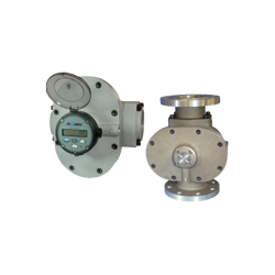
Large Capacity Oval Gear Meters (OM series)

The Large Oval Gear Meters from FLOMEC offer the ability to handle a wide range of fluid viscosities because of the increased flow range and offers you exceptional levels of repeatability. The large meter is often used for larger vessels and bunker applications for diesel measurement. 
Furthermore, these flowmeters are accurate, inexpensive in procurement, installation and maintenance.

More advantages:

  • Direct volumetric reading, which gives high accuracy and repeatability
  • Measures liquids both of high and low viscosity
  • No requirements for flow conditioning
  • Only two moving parts.

For sales or commercial inquiries please contact us at marine@insatech.com.

Contact us now

High accuracy and repeatability

The Oval gear meter is a precise positive displacement flowmeter incorporating a pair of
oval geared rotors. The meter is, therefore, independent of viscosity and density, which means that the same high accuracy is obtained regardless of changes in the physical parameters.

The high accuracy is also achieved because of the direct volumetric reading, which also gives a high degree of repeatability. 

Monitoring for precision

Oval Gear flowmeters are available as blind meters with a pulse signal output capable of
interfacing to most monitoring and control instrumentation.
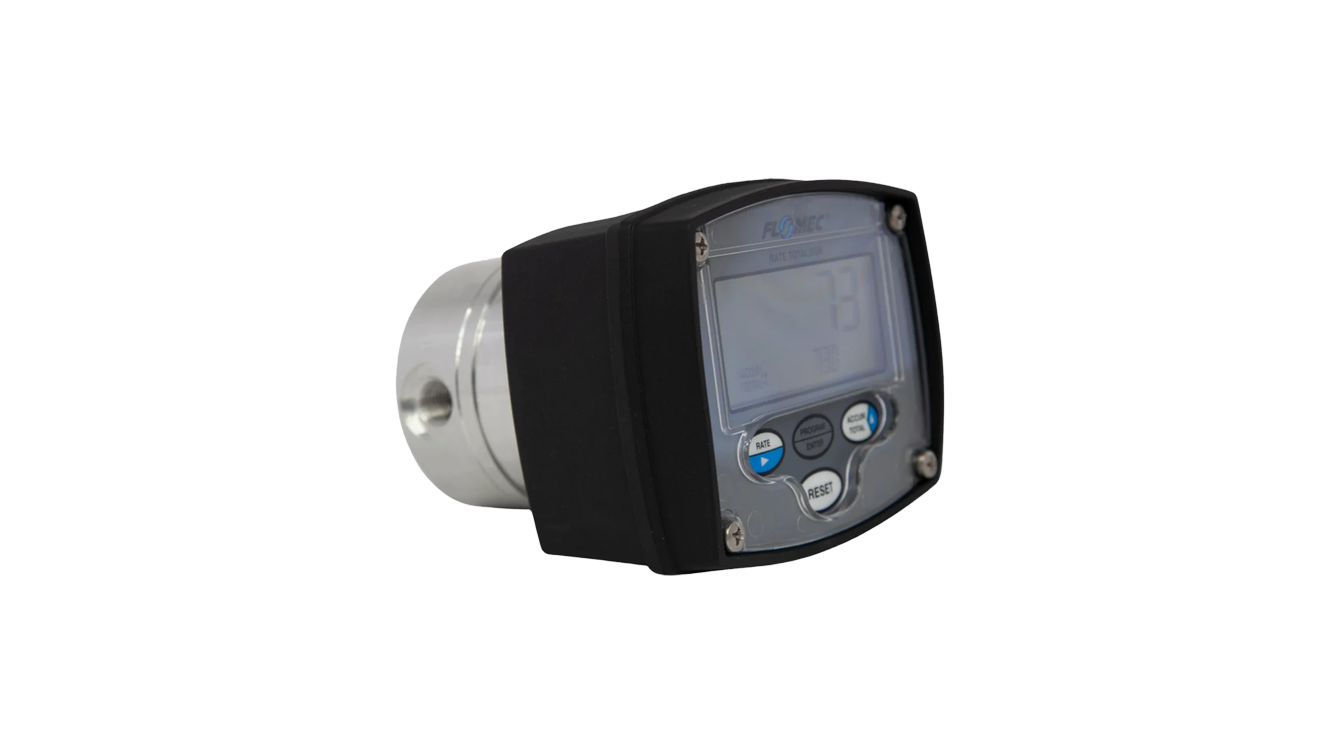
Or the meter can be fitted with instruments such as totalizers, rate totalizers or batch controllers.

These instruments also have monitoring and control output options including 4-20mA, scaled pulse, flow-rate
alarms and batch control logic (preset metering).

Flomec OM Large 1024X16x9

Typical Applications

For marine applications the large sized oval gear flow meter is often used for larger vessels and bunker applications for diesel measurement. 

These flowmeters are capable of measuring the flow of a broad range of liquids; 

  • Oils
  • Fuel
  • Batching
  • Diesel
  • Bunker C Fuel Oil
  • Industrial Fluids
  • Clean Fluids
  • Chemical Feed Lines
  • Truck metering
  • Chemical Additive Injection.

Does it match your need - contact us here

Usage in the maritime industry

Flomec OM-series is especially suitable for flow measurement / dosing of more viscous liquids such as oils, fuels and bunker C Fuel Oil.

Measure your fuel consumption

For an application such as fuel supply to a surplus dosing engine, both flow and return flow must be measured to achieve net consumption.

In addition, the temperature must be measured for volume compensation. For this we also provide temperature sensors and flow computers with standard API / ASTM tables defining the different fuel types.

Setting up a system using the OM-series flowmeter provide you with an accurate and reliable measurement of its fuel consumption.

Get more information here

Inside Engine Room On Big Ship

Choose the right Flowmeter

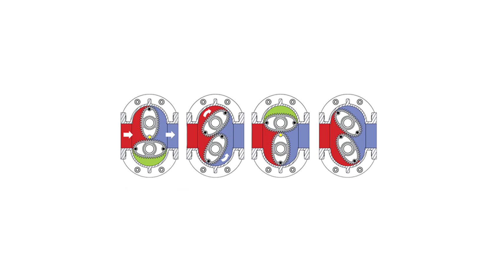
The Oval Gear Meters use a measuring principle, where a pair of oval-shaped gears in a measuring chamber rotate by the force of the liquid on these. The liquid flows into a chamber and is sealed off once the chamber is full and produces either an electronic pulse or drives a gear to register the volume as it exits the chamber. 

As illustrated in the example on the right, the pulse is generated because the (green) liquid is sealed from both the inlet (red liquid) and exit (blue liquid). This set up would produce four pulses as the meter transmits four identical volumes for every cycle. 

Thus, it matters which Flowmeter you choose; the:

This matters because the simplest meters register each time a bucket is filled. Here the total volume would be the sum of the number of buckets filled. In the complex meters the discrete volumes passed each time can be summed together to see the overall volume passing through the meter.

See all Oval Gear Flow Meters here
Insatech Medarbejdere Website MSR
For technical questions

Martin Søvind Jensen


Tel: +45 2761 4502

Email: Martin.Sovind@insatech.com

Write to Martin

Insatech Medarbejdere Website ASMI
For commercial inquiries

Astrid Mihut


Tel.: +45 5537 2095

Email: Marine@insatech.com


Contact us now

Technical Specifications
Normal Size

3"(75 mm) - 4"(100 mm)

Flow range

10 GPM(35 L/min) - 600 GPM(2500 L/min)

Accuracy+ @ 3cp

± 1.0% of reading (accuracy is ± 0.2% of reading with optional RT14 with non-linearity correction)

Repeatability

Typically ± 0.03% of reading

Temperature Range:

-40° F to +300° F (-40° C to +150° C)

Model/ Type
Product Identifier
  • OM004: 1/8" (4mm) Oval Gear Meter, 1-36 L/hr, 0.26-9.5 USG/hr
  • OM006: 1/4" (6mm) Oval Gear Meter, 2-100 L/hr, 0.53-26.4 USG/hr
  • OM008: 3/8" (8mm) Oval Gear Meter, 15-550 L/hr, 4-145 USG/hr
  • OM015: 1/2” (15mm) Oval Gear Meter, 1-40 L/min, 0.26-10.6 USG/min
  • OM025: 1” (25mm) Oval Gear Meter, 10-150 L/min, 2.6-40 USG/min
  • OM040: 1.5” (40mm) Oval Gear Meter, 15-250 L/min, 4-66 USG/min
  • OM050: 2” (50mm) Oval Gear Meter, 30-450 L/min, 8-120 USG/min
  • OM080: 3” (80mm) Oval Gear Meter, 50-1000 L/min, 13-260 USG/min
  • OM100: 4” (100mm) Oval Gear Meter, 75-1500 L/min, 20-400 USG/min
  • OM100: 4” (100mm) Oval Gear Meter, 150-2500 L/min, 40-660 USG/min
Body Material
  • A: Aluminium
  • E: Extended flow Aluminium
  • M: Intermediate pressure aluminium
  • N: Intermediate pressure Stainless Steel
  • S: Stainless Steel
  • P: PPS (PPS rotors only, temp code 8, BSP/NPT, safe area only)
Rotor/ Bearing Material
  • 00: PPS (not suitable for Temp code 3)
  • 10: High Viscosity PPS (not suitable for Temp code 3)
  • 44: Aluminium/Hardened Steel Roller Bearing (100E only)
  • 51: Stainless Steel / Carbon Ceramic Bearing
  • 71: High Viscosity Stainless Steel / Carbon Ceramic Bearing
Seal Material
  • 1: Viton (-15° C min. [5° F])
  • 3: Teflon Encapsulated Viton / Kalrez (-15° C min. [5° F])
  • 4: Nitrile (not suited Temp Code 3) (-40° C min. [-40° F])
Temperature Rating
  • 2: 120° C max. [250° F]
  • 3: 150° C max. [300° F] - Hall only, includes SS terminal cover
  • 5: Cooling fin for meters with integral display (For temperatures between 80-120° C [176-250° F])
  • 8: 80° C max. [176° F] - select for meters with display, OM008 with PPS rotors, and OM025P
Process Connection
  • 0: No fittings
  • 1: BSPP (G) female threaded (ISO 228)
  • 2: NPT female threaded
  • 3: Tri-clamp ferrules (1/2" larger than meter size)
  • 4: ANSI-150 RF flanged
         ANSI-150 RF flanged - SS Meters
  • 5: ANSI-300 RF flanged
  • 6: PN16 DIN flanged
         DIN flanged - SS Meters
Cable Entry
  • 1: M20 x 1.5mm (M16 x 1.5mm for R4)
  • 2: 1/2" NPT
  • 6: 3 x 16mm drilled holes (for R7/F15/F18/F19/F31)
Intregral Option
  • (DEFAULT): Reed switch & Hall Effect (NPN) outputs
  • SS: Stainless steel terminal cover
  • RS: Reed Switch only (Note 4)
  • E1: IECEx/ATEX Explosionproof EXd IIB T6…T3 Gb (Note 4)
  • E2: IECEx/ATEX Explosionproof EXd I/IIB T6…T3 Gb (SS meters only)
  • FP: cFMus Approved, USA and Canada, Flameproof Class 1 Zone 1 (Note 4)
  • QP: Quadrature pulse (2x NPN outputs)
  • QPN: Quadrature pulse (2x NPN outputs) with. Australian / New-Zealand weights and measures approval
  • Q1: Combination of E1 and QP Integral Options
  • Q1N: Combination of E1 and QPN Integral Options
  • HR: High resolution Hall effect (NPN) output
  • H1: Combination of E1 and HR Integral Options
  • R4: RT40 backlit rate totaliser in Aluminium housing (Notes 1, 2) Requires Cable Entry option 1
  • R5: RT14 backlit rate totaliser with 4-20mA and pulse outputs, in GRN housing (Notes 1, 2)
  • R6: RT14 IECEx/ATEX Intrinsically Safe rate totaliser with 4-20mA and pulse outputs, in GRN housing (Notes 1, 2, 4)
  • R7: RT40 backlit rate totaliser in GRN housing (Notes 1, 2, 5)
  • B11: EB11 single stage batch controller in GRN housing (Notes 1, 2)
  • E18: E018 IECEx/ATEX EXd rate totaliser with 4-20mA and pulse outputs, HART communications, in an Aluminium housing (Notes 2, 3)
  • E19: E018 IECEx/ATEX EXd rate totaliser with 4-20mA and pulse outputs, HART communications, in a SS housing (Notes 2, 3)
  • F15: F115 bidirectional flow rate/totaliser, 4-20mA and pulse outputs, in a GRN housing (Notes 1, 2)
  • F18: F018 rate totaliser with 4-20mA and pulse outputs and HART communications, in a GRN housing (Notes 1, 2, 5)
  • F19: F018 Intrinsically Safe rate totaliser with 4-20mA and pulse outputs and HART communications, in a GRN housing (Notes 1, 2, 4, 5)
  • F31: Intrinsically Safe 2 stage batch controller (Notes 1, 2, 4, 5).


Calibration (for integral display models only)
  • (DEFAULT): Displays in Litres
  • G: Displays in US Gallons
Note(s)

Note 1. Temp code 5 (cooling fin) is required for integral instruments with operating temperature between 80-120° C [176-250° F]

Note 2. Temp code 8 is required for integral instruments with operating temperature up to 80° C max. [176° F]

Note 3. Not available with OM080, OM080E, OM100, OM100E

Note 4. Not available with OM025P

Note 5. Only available with Cable entry code 6

Note 6. OM050 with PPS rotors 30 - 500 L/min [8 - 130 USG/min] with lubricating liquids, not for NMI use.

Specifications & Manuals

  • Data Sheet - Large Oval Gear Flow Meters - Flomec
    English | pdf
  • Owners manual - Oval Gear flowmeter - Flomec
    English | pdf
  • Data Sheet - Fuel Consumtion System Marine - Flomec
    English | pdf
  • Data Sheet - Om Series Mechanical Flowmeter - Flomec
    English | pdf

Didn't you find what you were looking for? 

If you are looking for some specific material, please write to us. Then we will try to find it for you, and send it as soon as possible.

Fill out the contact form 

Consent for storing of submitted data *


This site is protected by reCAPTCHA and the Google Privacy Policy and Terms of Service apply.

To top

Search